I repaired a Fibonacci clock a while back, and I have been meaning to make my own ever since. I used OpenScad and Freecad to create the enclosure but had issues getting the interior frame to have even borders so it sat with all my other unfinished projects. Recently with some help from AI I have mostly finished it.
This is the Fibonacci Light Box (Original Project) V15 — a 3D printed box that takes the Fibonacci sequence and turns it into a clock.The following is AI generated drivel...
Why Fibonacci, though
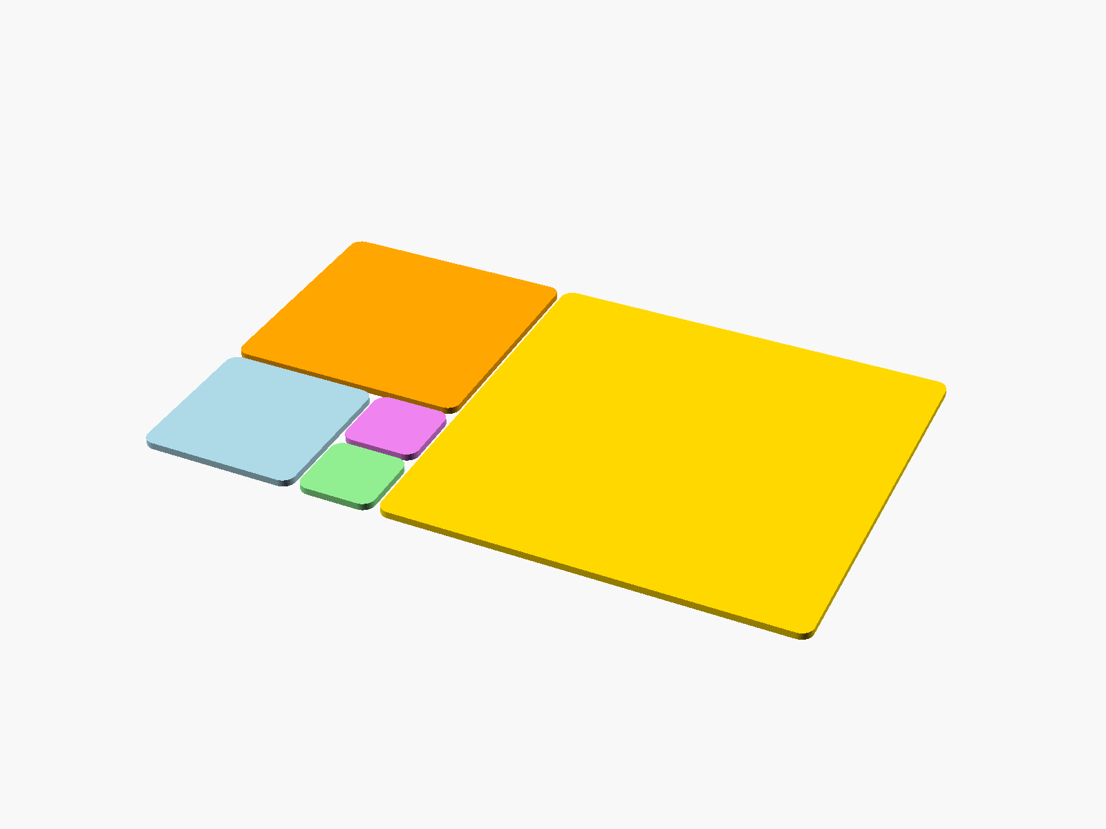 The Fibonacci sequence is 1, 1, 2, 3, 5, 8, 13 and so on — each number the sum of the two before it. Squares drawn at those sizes tile into a spiral you've probably seen in a hundred logos. The clock already used it to tell the time in coloured blocks. Building it as a physical object means the sequence stops being an abstraction and becomes something you can hang on a wall.
Making the chambers different sizes is also what makes the light interesting. Identical squares would look like a grid of tiles. Different squares, lit from behind, look like something you couldn't have planned.
What went into V15
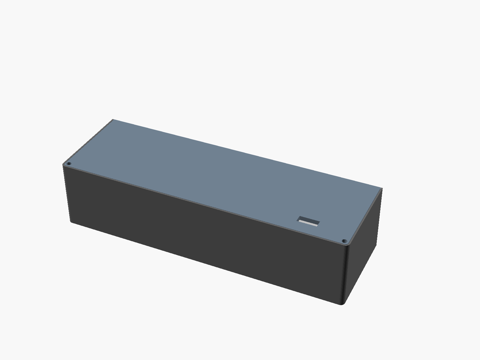 This is version fifteen. The previous one worked, but the wiring annoyed me — everything had to squeeze through a single hole in the base of the cassette, and the walls had big cutaways that made the whole thing feel flimsy.
This time the LED mounting base carries ten 8 × 2 mm slots, one pair per chamber, set near the top and bottom of each square. The wiring drops through those instead. The cutaways are gone entirely, and the old single entry hole with them. It's a small change on paper and a much better box in the hand.
The cassette is also held in place by the lid now, with no separate fasteners to lose.
The build
Four parts go together: the frame, the cassette, the backing plate and five coloured front plates. If you're printing one, do this in the right order. Set frame_width in the SCAD file to match your existing frame — default is 205 mm, minimum 150 mm — then print the tiny insert_test coupon and check your M3 heat-set inserts actually fit. Get that wrong after you've printed the frame and you're reprinting the frame.
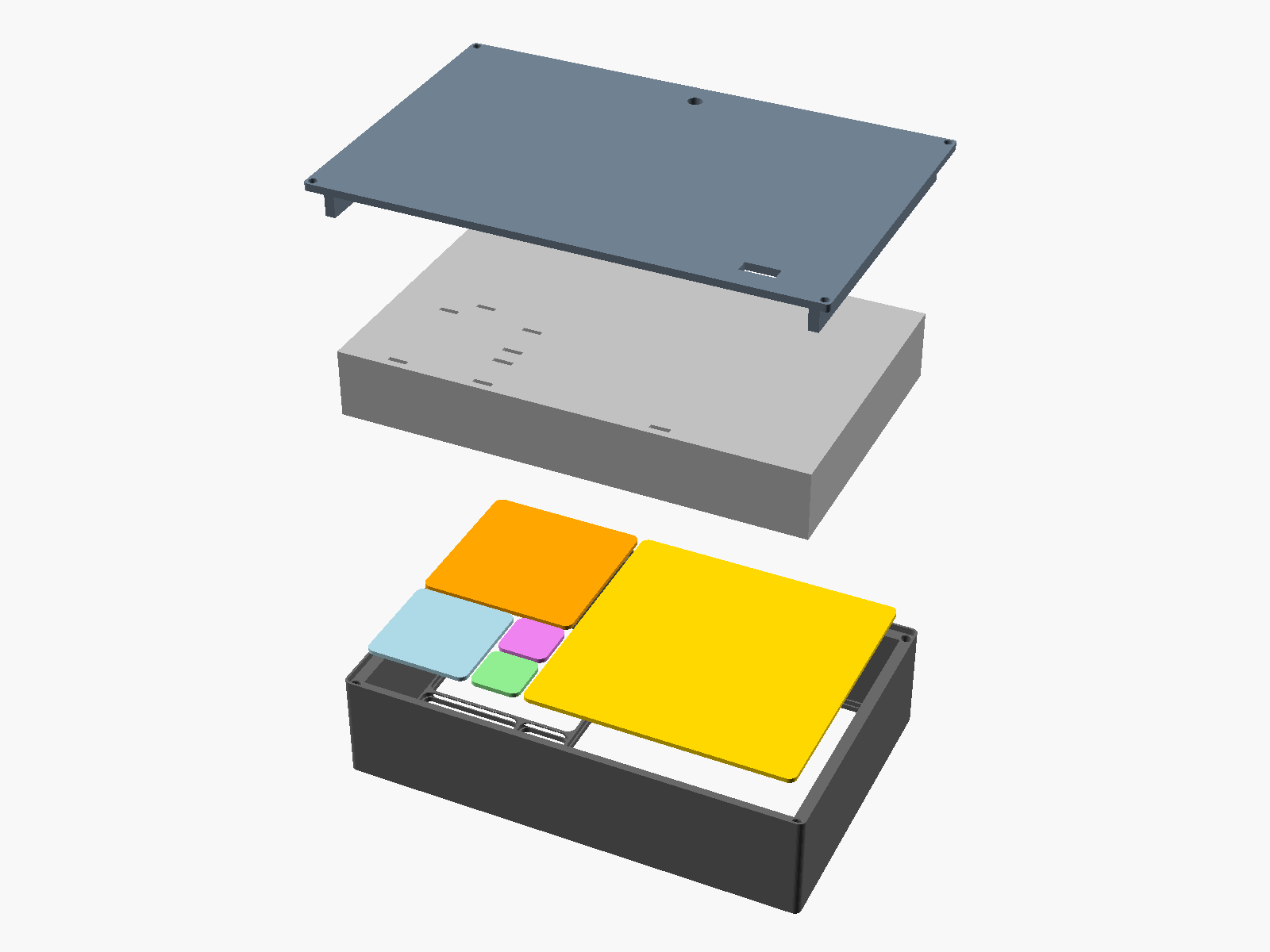
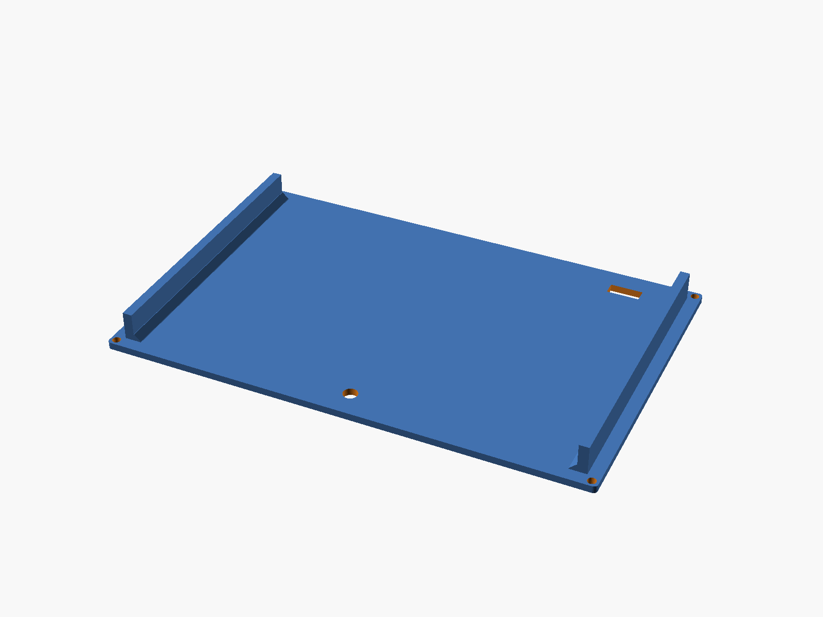
The chambers print roof-down with the openings facing up, so there's no bridging to fight with. On the left is the exploded stack — frame, plates, cassette, backing plate — and on the right the rear, with its reinforcement rails and the power socket cutout.
Lit up
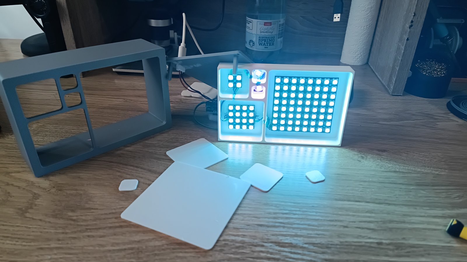
Behind each plate is an LED panel, fed through the paired slots. The diffusers spread the light evenly across each chamber, and because the chambers are different sizes the glow doesn't repeat.
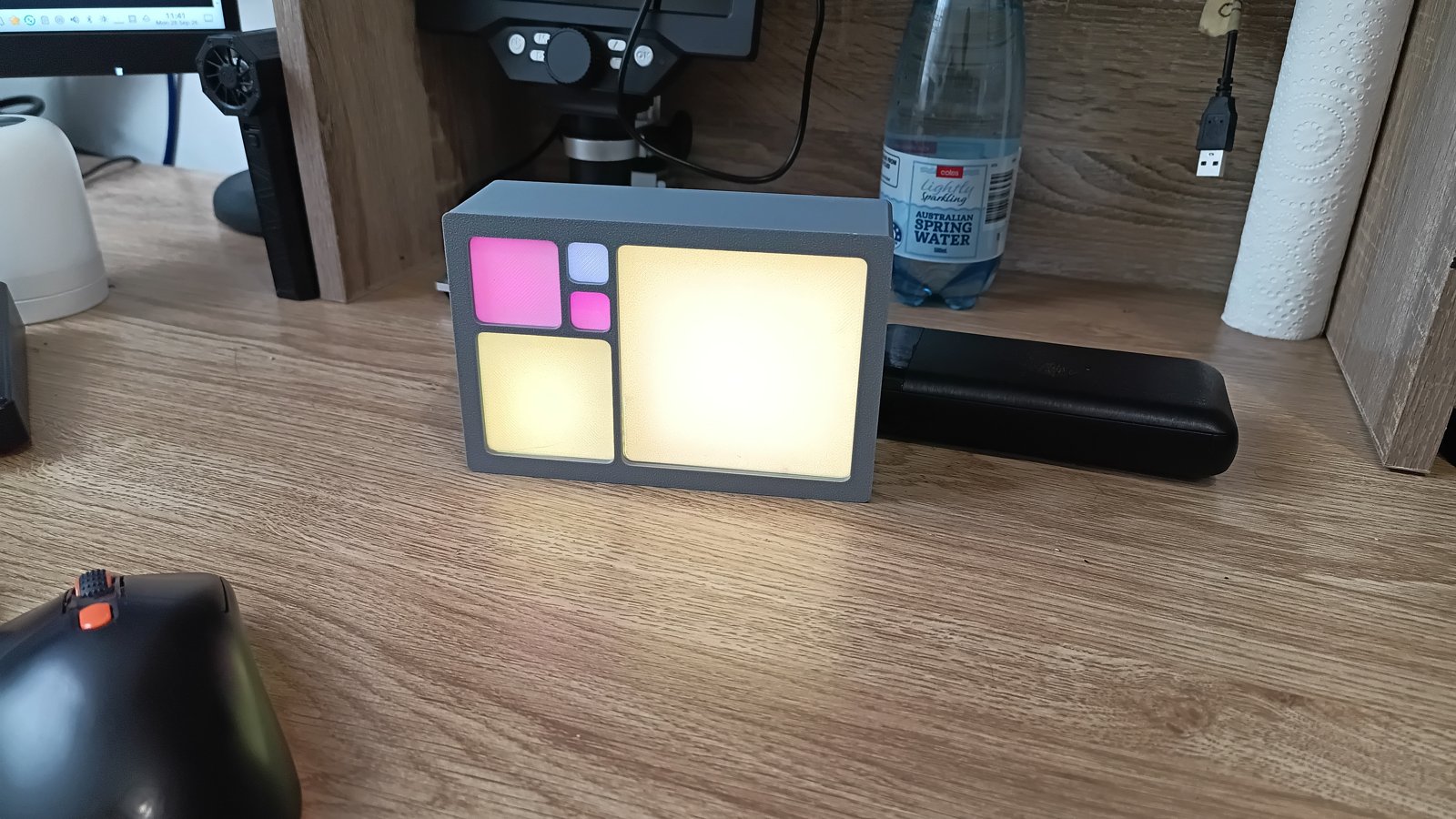
Change the colours and it's a completely different object.
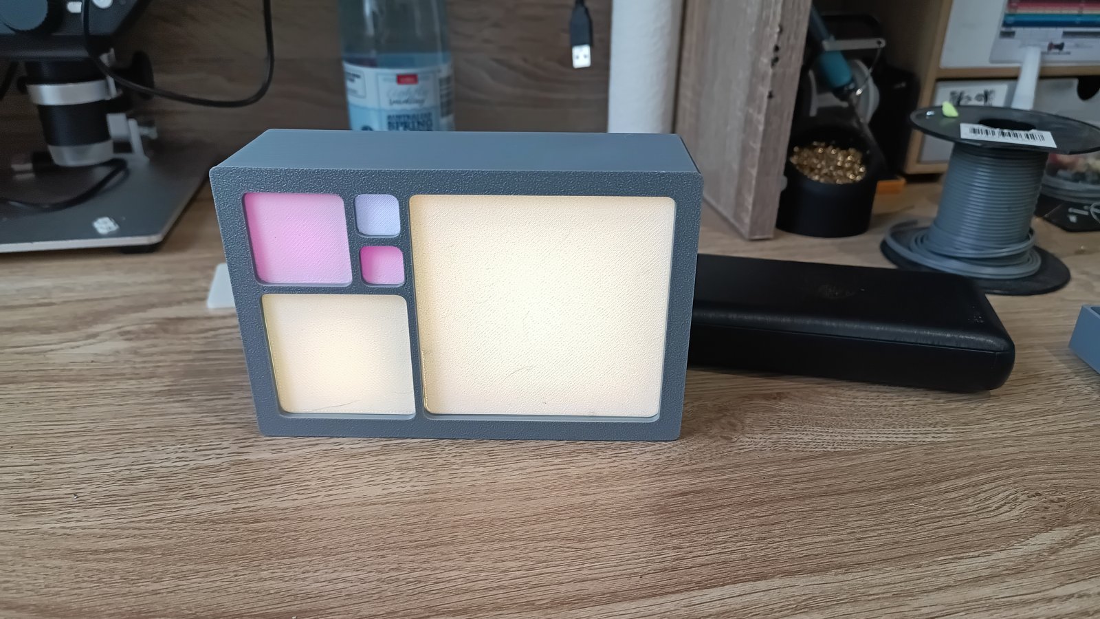
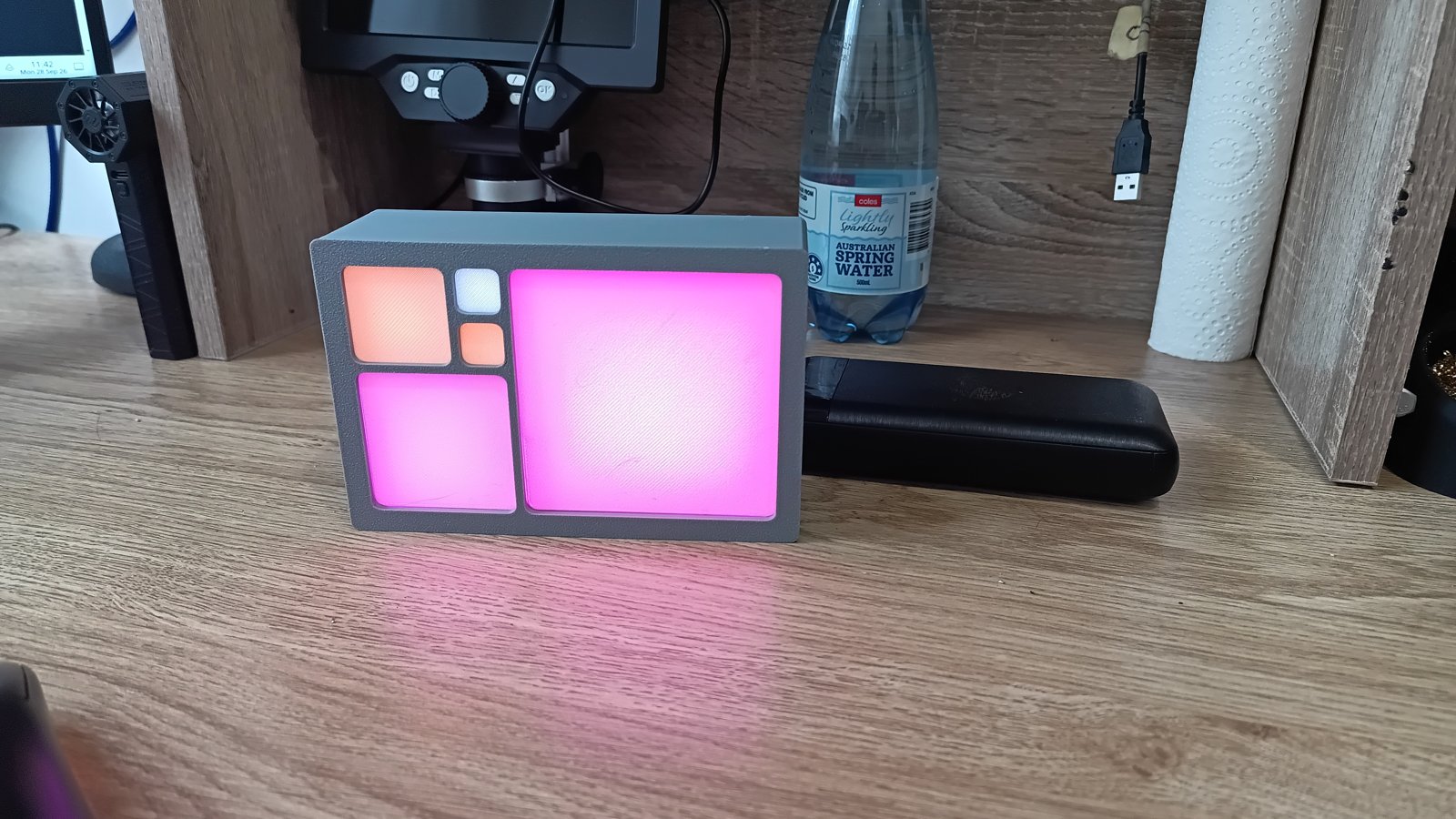
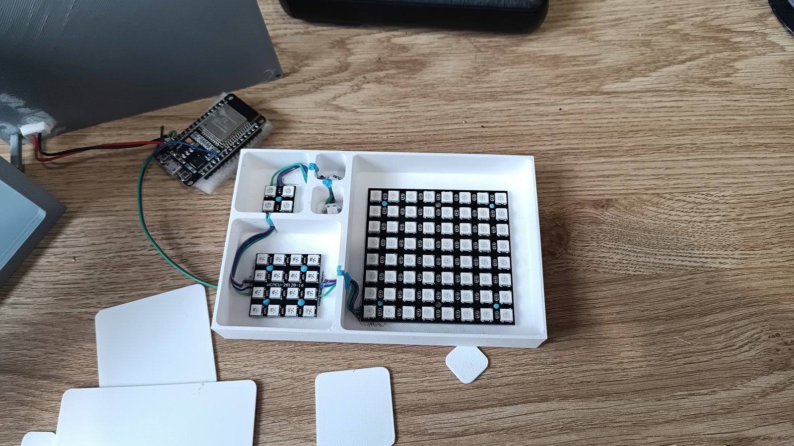
Open it up and you can see the LED panels and the board driving the whole thing.
The brains
The clock running it is a WiFi Fibonacci clock for the ESP8266/ESP32. It grabs the time over NTP so it's never wrong, sets itself up through WiFiManager rather than making you hardcode a network, carries 22 themes, updates over the air, and serves a web UI you can drive from your phone.
Source is on GitHub if you want to build one: github.com/kazakhan/FibonacciClock. GPL-2.0, so go mad. STLs and the OpenSCAD file are ready — set the frame width, print the coupon, and enjoy a box that looks like it was built by someone far more organised than me.